Low level architecture
Presentation
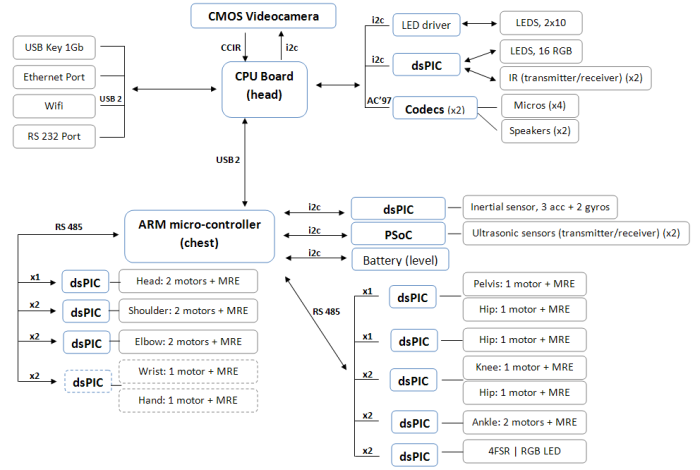
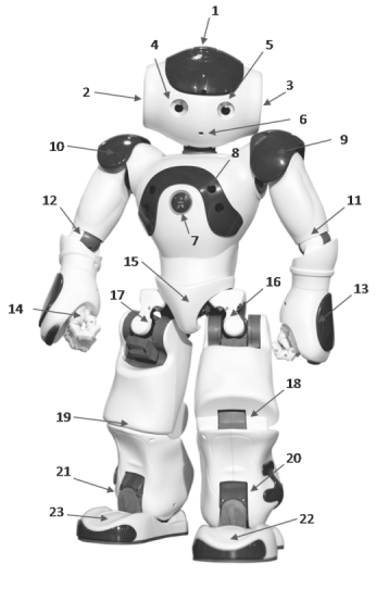
In order to understand the use of the DCM, we need an overview of all the devices in the robot.
Electronics architecture:
Device and subDevice definitions
Devices and subDevices are abstract definitions of objects used by the DCM.
Devices are subDevice controllers. The DCM communicates with them.
They are mainly electronic boards in the robot, with their micro-controller. Each device is defined by a bus type and an address on this bus. It also has an unique name and a type.
A subDevice is mainly an actuator or a sensor controlled by a device.
A subDevice is defined by its device, a subDevice type, and a subDevice number. This number is used because there is often more than one subDevice of the same type controlled by the one same device (for example a board with 3 LEDs). It starts at 1 (not 0) and increments. Each subDevice has a unique name (different from the Device one). This name is used for the communication with the upper level.
Both devices and subDevices have a series of keys with a unique value (usually a float, but it could be int, boolean or string) for each of the keys. Keys are for example “Value” (the main value), “Min”, “Max”, “Gain”, “Offset”, “Error”... There are some mandatory keys for devices and subDevices, but there could be many others, depending on the subDevice or the Device type.
If you add a prefix with the subDevice or Device name and the specific key name, you’ll have the string name of the subDevice key directly stored in ALMemory or the string name that you can send to the DCM for actuator change.
LED example:
“Face/Led/Red/Right/0Deg/Actuator”: This is the name of one of the LED actuator, the red LED near the right eyes at 0 angle.
This LED has a main value key named “Value”, this is a float from 0.0 (no light) to 1.0 (full light).
If you add the prefix, that is for subDevice :”Device/SubDeviceList/”, you have the complete key name: “Device/SubDeviceList/Face/Led/Red/Right/0Deg/Actuator/Value”
In ALMemory this is the key name that you can use to get the current LED value.
You can also use this name to send a timed-command value to the DCM for this actuator (for this precise use, the prefix is not mandatory).
Joint sensor example:
“LShoulderPitch/Position/Sensor”: This is the name of one of the joint angle sensor (Left shoulder pitch).
This joint has a main value key named “Value”, this is a float that is the angle in radian.
If you add the prefix, that is for subDevice:”Device/SubDeviceList/”, you have the complete key name: “Device/SubDeviceList/LShoulderPitch/Position/Sensor/Value”
In ALMemory this is the key name that you can use to get the current joint position value.
The joint sensor has also other key like “SensorType” ( “Device/SubDeviceList/LShoulderPitch/Position/Sensor/SensorType”). This is a configuration key that describes the kind of sensor for this joint, used then by motorboard. It’s not a good idea to change it!
You’ll see in next chapters the Device and subDevices names and all their possible keys.
The upper level usually communicates through the DCM with subdevices names (sensors / actuators) and seldom with devices names. But you can get useful information from devices (specific errors, ACK / NACK...).
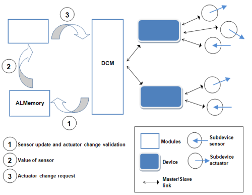
Note
This scheme is a virtual point of view. Hardware buses are not shown.
List of communication buses
Here is the list of possible communication buses for devices:
| Devices | Bus |
|---|---|
| MotherBoard | A virtual bus for devices in the motherboard. |
| MotherBoardI2C | I2C bus into the head |
| Chest | A virtual bus for devices in the chest. |
| ChestI2C | I2C bus into the robot body. |
| RS485Down | RS485 bus for all boards in legs. |
| RS485Up | RS485 bus for all boards in arms/neck. |
| LeftHandI2C | Not implemented |
| RightHandI2C | Not implemented |
This is only useful if you want to understand the preference (configuration) file.
Type of device
Here is the list of possible devices:
| Device | Is ... |
|---|---|
| MotherBoard | The main CPU board in the head with the Geode processor. |
| ChestBoard | The chest board with the ARM processor. |
| MotorBoard | All motor board in the robot that control joints, except for foot and hand. They are specific. |
| MotorBoardHand | Motor board for the hands. Right now strictly equivalent to MotorBoard. |
| MotorBoardFoot | Motor board for the foots. Since the first released version of NAO, these boards do not manage motors anymore. |
| TouchBoard | The board with capacitive sensors at the top of the head. |
| FaceBoard | The board around the eyes of the robot, with LEDs and IR. |
| USBoard | The board with the ultrasonic sensors. |
| InertialSensor | The board with the accelerometer / gyrometer sensors. |
| EarLeds | The board that controls LEDs in both ears. |
| Battery | The board inside the battery. |
This is only useful if you want to understand the preference (configuration) file.
Type of subdevice
Here is the list of possible subDevices:
| Type | SubDevice | Is ... |
|---|---|---|
| Actuators | Joint | the actuator that allows you to control the angle of one robot joint. |
| JointHardness | an actuator that controls the percentage of the total power sent to the motor to control the joint. It’s 0% at the beginning and 100% at normal use (the value is from 0.0 to 1.0). Use this to have smooth increase/decrease of joint control. Hardness is defined as stiffness in motion. | |
| Led | a basic LED (one color) where you can control the value from 0 to 100% (0.0 to 1.0). | |
| Power | not implemented | |
| Charge | not implemented | |
| UsSend | an actuator that allows you to send an ultrasonic wave, waiting for the sensor result. | |
| Sensors | JointPosition | the sensor value for the angle position of one robot joint. |
| Current | the electric current for one motor of a specific joint. | |
| FSR | the weight on the FSR sensor (or on all the foot) | |
| CenterOfPressure | the position of the force applied on one foot. | |
| Touch | state of capacitive proximity switch (press = 1.0 or release = 0.0) | |
| ChestState | not implemented | |
| USReceived | the ultrasonic distance sensor result. Received after a wave is sent with the UsSend actuator. | |
| Accelerometer | the result of one accelerometer axis (acceleration). | |
| Gyrometer | the result of one gyrometer axis (rotation speed). | |
| Angle | an angle of the robot, returned by the inertial board. | |
| Temperature | temperature result for each motor (simulation) or the battery (sensor). | |
| Switch | switch state (press = 0.0 or release = 1.0) for chest button or foot bumpers. | |
| Battery | the battery state sensor (mainly charge). |
List of devices
This is all device name/type/busNumber on the robot. They are mainly electronic boards.
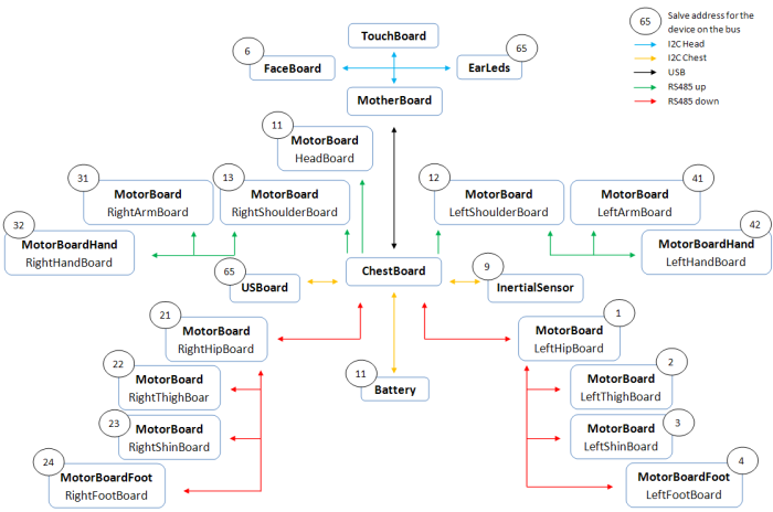
Note
The HeadBoard and the Battery can have the same address as they are not on the same bus.
Note
New Sanyo battery has I2C address 52.
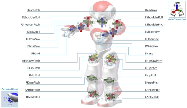
Joint names
Here is the list of all joint names.
These names are used for all joints subDevices. A motorBoard controls one or two joints.
List of subDevices
Here is the list of all the subDevices of the robot.
The number is the subDevice Number. This is not useful, unless you want to understand the preference (configuration) file.
In ALMemory, the name of these subDevices are prefixed by “Device/SubDeviceList/”.
Note
This is only the subDevice list. For all keys and meaning of values, see Description of the mandatory and specific ALMemory keys for each subDevice type.
1. touchBoard
subDevices linked to the touchBoard device (only on Academics Edition).
There are 3 tactile sensors on the head, each return 0 or 1 if a finger is coming near. It may react differently if the battery is connected to its charger. There are also 12 blue LEDs.
| Name | Type | Number |
|---|---|---|
| Head/Touch/Front/Sensor | Touch | 1 |
| Head/Touch/Rear/Sensor | Touch | 2 |
| Head/Touch/Middle/Sensor | Touch | 3 |
| Head/Led/Rear/Left/0/Actuator | Led | 4 |
| Head/Led/Rear/Left/1/Actuator | Led | 5 |
| Head/Led/Rear/Left/2/Actuator | Led | 6 |
| Head/Led/Rear/Right/2/Actuator | Led | 7 |
| Head/Led/Rear/Right/1/Actuator | Led | 8 |
| Head/Led/Rear/Right/0/Actuator | Led | 9 |
| Head/Led/Middle/Right/0/Actuator | Led | 10 |
| Head/Led/Front/Right/0/Actuator | Led | 11 |
| Head/Led/Front/Right/1/Actuator | Led | 12 |
| Head/Led/Front/Left/1/Actuator | Led | 13 |
| Head/Led/Front/Left/0/Actuator | Led | 14 |
| Head/Led/Middle/Left/0/Actuator | Led | 15 |
2. EarLeds - Right
subDevices linked to the device EarLeds.
There are 10 blue LEDs on each ear of the robot. Their name has left/right info and an angle 0° is toward up. <180° are toward the front of the robot (angles are approximate)
| Name | Type | Number |
|---|---|---|
| Ears/Led/Right/0Deg/Actuator | Led | 15 |
| Ears/Led/Right/36Deg/Actuator | Led | 14 |
| Ears/Led/Right/72Deg/Actuator | Led | 13 |
| Ears/Led/Right/108Deg/Actuator | Led | 12 |
| Ears/Led/Right/144Deg/Actuator | Led | 11 |
| Ears/Led/Right/180Deg/Actuator | Led | 20 |
| Ears/Led/Right/216Deg/Actuator | Led | 19 |
| Ears/Led/Right/252Deg/Actuator | Led | 18 |
| Ears/Led/Right/288Deg/Actuator | Led | 17 |
| Ears/Led/Right/324Deg/Actuator | Led | 16 |
3. EarLeds - Left
subDevices linked to the device EarLeds.
There are 10 blue LEDs on each ear of the robot. Their name has left/right info and an angle 0° is toward up. <180° are toward the front of the robot (angles are approximate)
| Name | Type | Number |
|---|---|---|
| Ears/Led/Left/0Deg/Actuator | Led | 5 |
| Ears/Led/Left/36Deg/Actuator | Led | 6 |
| Ears/Led/Left/72Deg/Actuator | Led | 7 |
| Ears/Led/Left/108Deg/Actuator | Led | 8 |
| Ears/Led/Left/144Deg/Actuator | Led | 9 |
| Ears/Led/Left/180Deg/Actuator | Led | 10 |
| Ears/Led/Left/216Deg/Actuator | Led | 1 |
| Ears/Led/Left/252Deg/Actuator | Led | 2 |
| Ears/Led/Left/288Deg/Actuator | Led | 3 |
| Ears/Led/Left/324Deg/Actuator | Led | 4 |
4. FaceBoard - Right
subDevices linked to the device FaceBoard.
There are 8 red, 8 green, and 8 blue LEDs on each eyes.
Their name has left/right info and an angle. 0 is toward up. <180° are toward the right side of the robot
| Name | Type | Number |
|---|---|---|
| Face/Led/Red/Right/0Deg/Actuator | Led | 15 |
| Face/Led/Red/Right/45Deg/Actuator | Led | 16 |
| Face/Led/Red/Right/90Deg/Actuator | Led | 9 |
| Face/Led/Red/Right/135Deg/Actuator | Led | 10 |
| Face/Led/Red/Right/180Deg/Actuator | Led | 11 |
| Face/Led/Red/Right/225Deg/Actuator | Led | 12 |
| Face/Led/Red/Right/270Deg/Actuator | Led | 13 |
| Face/Led/Red/Right/315Deg/Actuator | Led | 14 |
| Name | Type | Number |
|---|---|---|
| Face/Led/Green/Right/0Deg/Actuator | Led | 31 |
| Face/Led/Green/Right/45Deg/Actuator | Led | 32 |
| Face/Led/Green/Right/90Deg/Actuator | Led | 25 |
| Face/Led/Green/Right/135Deg/Actuator | Led | 26 |
| Face/Led/Green/Right/180Deg/Actuator | Led | 27 |
| Face/Led/Green/Right/225Deg/Actuator | Led | 28 |
| Face/Led/Green/Right/270Deg/Actuator | Led | 29 |
| Face/Led/Green/Right/315Deg/Actuator | Led | 30 |
| Name | Type | Number |
|---|---|---|
| Face/Led/Blue/Right/0Deg/Actuator | Led | 47 |
| Face/Led/Blue/Right/45Deg/Actuator | Led | 48 |
| Face/Led/Blue/Right/90Deg/Actuator | Led | 41 |
| Face/Led/Blue/Right/135Deg/Actuator | Led | 42 |
| Face/Led/Blue/Right/180Deg/Actuator | Led | 43 |
| Face/Led/Blue/Right/225Deg/Actuator | Led | 44 |
| Face/Led/Blue/Right/270Deg/Actuator | Led | 45 |
| Face/Led/Blue/Right/315Deg/Actuator | Led | 46 |
5. FaceBoard - Left
subDevices linked to the device FaceBoard.
There are 8 red, 8 green, and 8 blue LEDs on each eye.
Their name has left/right info and an angle. 0 is toward up. <180° are toward the right side of the robot.
| Name | Type | Number |
|---|---|---|
| Face/Led/Red/Left/0Deg/Actuator | Led | 3 |
| Face/Led/Red/Left/45Deg/Actuator | Led | 4 |
| Face/Led/Red/Left/90Deg/Actuator | Led | 5 |
| Face/Led/Red/Left/135Deg/Actuator | Led | 6 |
| Face/Led/Red/Left/180Deg/Actuator | Led | 7 |
| Face/Led/Red/Left/225Deg/Actuator | Led | 8 |
| Face/Led/Red/Left/270Deg/Actuator | Led | 1 |
| Face/Led/Red/Left/315Deg/Actuator | Led | 2 |
| Name | Type | Number |
|---|---|---|
| Face/Led/Green/Left/0Deg/Actuator | Led | 19 |
| Face/Led/Green/Left/45Deg/Actuator | Led | 20 |
| Face/Led/Green/Left/90Deg/Actuator | Led | 21 |
| Face/Led/Green/Left/135Deg/Actuator | Led | 22 |
| Face/Led/Green/Left/180Deg/Actuator | Led | 23 |
| Face/Led/Green/Left/225Deg/Actuator | Led | 24 |
| Face/Led/Green/Left/270Deg/Actuator | Led | 17 |
| Face/Led/Green/Left/315Deg/Actuator | Led | 18 |
| Name | Type | Number |
|---|---|---|
| Face/Led/Blue/Left/0Deg/Actuator | Led | 35 |
| Face/Led/Blue/Left/45Deg/Actuator | Led | 36 |
| Face/Led/Blue/Left/90Deg/Actuator | Led | 37 |
| Face/Led/Blue/Left/135Deg/Actuator | Led | 38 |
| Face/Led/Blue/Left/180Deg/Actuator | Led | 39 |
| Face/Led/Blue/Left/225Deg/Actuator | Led | 40 |
| Face/Led/Blue/Left/270Deg/Actuator | Led | 33 |
| Face/Led/Blue/Left/315Deg/Actuator | Led | 34 |
6. HeadBoard
subDevices linked to the device HeadBoard.
There are here two joints, with all their actuators/sensors:
Joint HeadPitch:
| Name | Type | Number |
|---|---|---|
| HeadPitch/Position/Actuator | Joint | 1 |
| HeadPitch/Hardness/Actuator | JointHardness | 1 |
| HeadPitch/Position/Sensor | jointPosition | 1 |
| HeadPitch/ElectricCurrent/Sensor | Current | 1 |
| HeadPitch/Temperature/Sensor | Temperature | 1 |
Joint HeadYaw:
| Name | Type | Number |
|---|---|---|
| HeadYaw/Position/Actuator | Joint | 2 |
| HeadYaw/Hardness/Actuator | JointHardness | 2 |
| HeadYaw/Position/Sensor | jointPosition | 2 |
| HeadYaw/ElectricCurrent/Sensor | Current | 2 |
| HeadYaw/Temperature/Sensor | Temperature | 2 |
7. ChestBoard, and Battery
subDevices linked to the device ChestBoard, and the Battery.
The ChestBoard has many subDevices: 3 LEDs, battery, button.
There are here two joints, with all their actuators/sensors.
LEDs:
| Name | Type | Number |
|---|---|---|
| ChestBoard/Led/Red/Actuator | Led | 1 |
| ChestBoard/Led/Green/Actuator | Led | 2 |
| ChestBoard/Led/Blue/Actuator | Led | 3 |
Power/status:
| Name | Type | Number |
|---|---|---|
| ChestBoard/Power/Actuator | Led | 1 |
| ChestBoard/ChestState/Actuator | Led | 1 |
Note
This is not implemented yet.
Button:
| Name | Type | Number |
|---|---|---|
| ChestBoard/Button/Sensor | Switch | 1 |
The Battery Device has 3 subDevices:
| Name | Type | Number |
|---|---|---|
| Battery/Charge/Sensor | Battery | 1 |
| Battery/ElectricCurrent/Sensor | Current | 1 |
| Battery/Temperature/Sensor | Temperature | 1 |
Note
The Temperature subdevice is not implemented yet, except in the new Sanyo battery.
8. USBoard
subDevices linked to the USBoard device.
There is an actuator to send an ultrasonic wave, and a sensor for the result.
| Name | Type | Number |
|---|---|---|
| US/Actuator | UsSend | 1 |
| US/Sensor | USReceived | 1 |
| US/Left/Sensor | USReceived | 1 |
| US/Right/Sensor | USReceived | 1 |
SubDevices linked to the InertialSensor device:
The inertial sensor board has a 3 axes accelerometer and a 2 axis Gyrometer. It also returns a computed angle, computed with an internal algorithm.
| Name | Type | Number |
|---|---|---|
| InertialSensor/AccX/Sensor | Accelerometer | 1 |
| InertialSensor/AccY/Sensor | Accelerometer | 2 |
| InertialSensor/AccZ/Sensor | Accelerometer | 3 |
| InertialSensor/GyrX/Sensor | Gyrometer | 1 |
| InertialSensor/GyrY/Sensor | Gyrometer | 2 |
| InertialSensor/GyrRef/Sensor | Gyrometer | 3 |
| InertialSensor/AngleX/Sensor | Angle | 1 |
| InertialSensor/AngleY/Sensor | Angle | 2 |
Note
These 2 last subDevices are now implemented.
9. LeftShoulderBoard
SubDevices linked to the LeftShoulderBoard devices.
There are here two joints, with all their actuators/sensors.
LShoulderPitch joint:
| Name | Type | Number |
|---|---|---|
| LShoulderPitch/Position/Actuator | Joint | 1 |
| LShoulderPitch/Hardness/Actuator | JointHardness | 1 |
| LShoulderPitch/Position/Sensor | jointPosition | 1 |
| LShoulderPitch/ElectricCurrent/Sensor | Current | 1 |
| LShoulderPitch/Temperature/Sensor | Temperature | 1 |
LShoulderRoll joint:
| Name | Type | Number |
|---|---|---|
| LShoulderRoll/Position/Actuator | Joint | 2 |
| LShoulderRoll/Hardness/Actuator | JointHardness | 2 |
| LShoulderRoll/Position/Sensor | jointPosition | 2 |
| LShoulderRoll/ElectricCurrent/Sensor | Current | 2 |
| LShoulderRoll/Temperature/Sensor | Temperature | 2 |
10. RightShoulderBoard
SubDevices linked to the RightShoulderBoard device.
There are here two joints, with all their actuators/sensors.
RShoulderPitch joint:
| Name | Type | Number |
|---|---|---|
| RShoulderPitch/Position/Actuator | Joint | 1 |
| RShoulderPitch/Hardness/Actuator | JointHardness | 1 |
| RShoulderPitch/Position/Sensor | jointPosition | 1 |
| RShoulderPitch/ElectricCurrent/Sensor | Current | 1 |
| RShoulderPitch/Temperature/Sensor | Temperature | 1 |
RShoulderRoll joint:
| Name | Type | Number |
|---|---|---|
| RShoulderRoll/Position/Actuator | Joint | 2 |
| RShoulderRoll/Hardness/Actuator | JointHardness | 2 |
| RShoulderRoll/Position/Sensor | jointPosition | 2 |
| RShoulderRoll/ElectricCurrent/Sensor | Current | 2 |
| RShoulderRoll/Temperature/Sensor | Temperature | 2 |
11. LeftArmBoard
subDevices linked to the LeftArmBoard device.
There are here two joints, with all their actuators/sensors.
LElbowRoll joint:
| Name | Type | Number |
|---|---|---|
| LElbowRoll/Position/Actuator | Joint | 1 |
| LElbowRoll/Hardness/Actuator | JointHardness | 1 |
| LElbowRoll/Position/Sensor | jointPosition | 1 |
| LElbowRoll/ElectricCurrent/Sensor | Current | 1 |
| LElbowRoll/Temperature/Sensor | Temperature | 1 |
LElbowYaw joint:
| Name | Type | Number |
|---|---|---|
| LElbowYaw/Position/Actuator | Joint | 2 |
| LElbowYaw/Hardness/Actuator | JointHardness | 2 |
| LElbowYaw/Position/Sensor | jointPosition | 2 |
| LElbowYaw/ElectricCurrent/Sensor | Current | 2 |
| LElbowYaw/Temperature/Sensor | Temperature | 2 |
12. RightArmBoard
SubDevices linked to the RightArmBoard device.
There are here two joints, with all their actuators/sensors.
RElbowRoll joint:
| Name | Type | Number |
|---|---|---|
| RElbowRoll/Position/Actuator | Joint | 1 |
| RElbowRoll/Hardness/Actuator | JointHardness | 1 |
| RElbowRoll/Position/Sensor | jointPosition | 1 |
| RElbowRoll/ElectricCurrent/Sensor | Current | 1 |
| RElbowRoll/Temperature/Sensor | Temperature | 1 |
RElbowYaw joint:
| Name | Type | Number |
|---|---|---|
| RElbowYaw/Position/Actuator | Joint | 2 |
| RElbowYaw/Hardness/Actuator | JointHardness | 2 |
| RElbowYaw/Position/Sensor | jointPosition | 2 |
| RElbowYaw/ElectricCurrent/Sensor | Current | 2 |
| RElbowYaw/Temperature/Sensor | Temperature | 2 |
13. LeftHandBoard
SubDevices linked to the LeftHandBoard devices.
There are here two joints, with all their actuators/sensors.
LWristYaw joint:
| Name | Type | Number |
|---|---|---|
| LWristYaw/Position/Actuator | Joint | 1 |
| LWristYaw/Hardness/Actuator | JointHardness | 1 |
| LWristYaw/Position/Sensor | jointPosition | 1 |
| LWristYaw/ElectricCurrent/Sensor | Current | 1 |
| LWristYaw/Temperature/Sensor | Temperature | 1 |
LHand joint:
| Name | Type | Number |
|---|---|---|
| LHand/Position/Actuator | Joint | 2 |
| LHand/Hardness/Actuator | JointHardness | 2 |
| LHand/Position/Sensor | jointPosition | 2 |
| LHand/ElectricCurrent/Sensor | Current | 2 |
| LHand/Temperature/Sensor | Temperature | 2 |
Capacitive sensors:
| Name | Type | Number |
|---|---|---|
| LHand/Touch/Back/Sensor | TouchHand | 3 |
| LHand/Touch/Left/Sensor/ | TouchHand | 4 |
| LHand/Touch/Right/Sensor/ | TouchHand | 5 |
14. RightHandBoard
SubDevices linked to the RightHandBoard device.
There are here two joints, with all their actuators/sensors.
RWristYaw joint:
| Name | Type | Number |
|---|---|---|
| RWristYaw/Position/Actuator | Joint | 1 |
| RWristYaw/Hardness/Actuator | JointHardness | 1 |
| RWristYaw/Position/Sensor | jointPosition | 1 |
| RWristYaw/ElectricCurrent/Sensor | Current | 1 |
| RWristYaw/Temperature/Sensor | Temperature | 1 |
RHand joint:
| Name | Type | Number |
|---|---|---|
| RHand/Position/Actuator | Joint | 2 |
| RHand/Hardness/Actuator | JointHardness | 2 |
| RHand/Position/Sensor | jointPosition | 2 |
| RHand/ElectricCurrent/Sensor | Current | 2 |
| RHand/Temperature/Sensor | Temperature | 2 |
Capacitive sensors:
| Name | Type | Number |
|---|---|---|
| RHand/Touch/Back/Sensor | TouchHand | 3 |
| RHand/Touch/Left/Sensor/ | TouchHand | 4 |
| RHand/Touch/Right/Sensor/ | TouchHand | 5 |
15. HipBoard
SubDevices linked to the LeftHipBoard device.
There is here one joint, and its actuators/sensors.
LHipYawPitch and RHipYawPitch share the same motor so they move simultaneously and symmetrically.
LHipYawPitch joint:
| Name | Type | Number |
|---|---|---|
| LHipYawPitch/Position/Actuator | Joint | 2 |
| LHipYawPitch/Hardness/Actuator | JointHardness | 2 |
| LHipYawPitch/Position/Sensor | jointPosition | 2 |
| LHipYawPitch/ElectricCurrent/Sensor | Current | 2 |
| LHipYawPitch/Temperature/Sensor | Temperature | 2 |
16. LeftHipBoard
subDevices linked to the LeftHipBoard device.
There is here one joint, and its actuators/sensors.
LHipRoll joint:
| Name | Type | Number |
|---|---|---|
| LHipRoll/Position/Actuator | Joint | 1 |
| LHipRoll/Hardness/Actuator | JointHardness | 1 |
| LHipRoll/Position/Sensor | jointPosition | 1 |
| LHipRoll/ElectricCurrent/Sensor | Current | 1 |
| LHipRoll/Temperature/Sensor | Temperature | 1 |
17. RightHipBoard
subDevices linked to the RightHipBoard device.
There is here one joint, and its actuators/sensors.
RHipRoll joint:
| Name | Type | Number |
|---|---|---|
| RHipRoll/Position/Actuator | Joint | 1 |
| RHipRoll/Hardness/Actuator | JointHardness | 1 |
| RHipRoll/Position/Sensor | jointPosition | 1 |
| RHipRoll/ElectricCurrent/Sensor | Current | 1 |
| RHipRoll/Temperature/Sensor | Temperature | 1 |
18. LeftThighBoard
SubDevices linked to the LeftThighBoard device.
There are here two joints, with all their actuators/sensors.
LHipPitch joint:
| Name | Type | Number |
|---|---|---|
| LHipPitch/Position/Actuator | Joint | 1 |
| LHipPitch/Hardness/Actuator | JointHardness | 1 |
| LHipPitch/Position/Sensor | jointPosition | 1 |
| LHipPitch/ElectricCurrent/Sensor | jointPosition | 1 |
| LHipPitch/Temperature/Sensor | Temperature | 1 |
LKneePitch joint:
| Name | Type | Number |
|---|---|---|
| LKneePitch/Position/Actuator | Joint | 2 |
| LKneePitch/Hardness/Actuator | JointHardness | 2 |
| LKneePitch/Position/Sensor | jointPosition | 2 |
| LKneePitch/ElectricCurrent/Sensor | Current | 2 |
| LKneePitch/Temperature/Sensor | Temperature | 2 |
19. RightThighBoard
SubDevices linked to the RightThighBoard device.
There are here two joints, with all their actuators/sensors.
RHipPitch joint:
| Name | Type | Number |
|---|---|---|
| RHipPitch/Position/Actuator | Joint | 1 |
| RHipPitch/Hardness/Actuator | JointHardness | 1 |
| RHipPitch/Position/Sensor | jointPosition | 1 |
| RHipPitch/ElectricCurrent/Sensor | Current | 1 |
| RHipPitch/Temperature/Sensor | Temperature | 1 |
RKneePitch joint:
| Name | Type | Number |
|---|---|---|
| RKneePitch/Position/Actuator | Joint | 2 |
| RKneePitch/Hardness/Actuator | JointHardness | 2 |
| RKneePitch/Position/Sensor | jointPosition | 2 |
| RKneePitch/ElectricCurrent/Sensor | Current | 2 |
| RKneePitch/Temperature/Sensor | Temperature | 2 |
20. LeftShinBoard
SubDevices linked to the LeftShinBoard device.
There are here two joints, and its actuators/sensors.
LAnklePitch Joint:
| Name | Type | Number |
|---|---|---|
| LAnklePitch/Position/Actuator | Joint | 1 |
| LAnklePitch/Hardness/Actuator | JointHardness | 1 |
| LAnklePitch/Position/Sensor | jointPosition | 1 |
| LAnklePitch/ElectricCurrent/Sensor | Current | 1 |
| LAnklePitch/Temperature/Sensor | Temperature | 1 |
LAnkleRoll joint:
| Name | Type | Number |
|---|---|---|
| LAnkleRoll/Position/Actuator | Joint | 2 |
| LAnkleRoll/Hardness/Actuator | JointHardness | 2 |
| LAnkleRoll/Position/Sensor | jointPosition | 2 |
| LAnkleRoll/ElectricCurrent/Sensor | Current | 2 |
| LAnkleRoll/Temperature/Sensor | Temperature | 2 |
21. RightShinBoard
SubDevices linked to the RightShinBoard device.
There is here one joint, and its actuators/sensors.
RAnklePitch joint:
| Name | Type | Number |
|---|---|---|
| RAnklePitch/Position/Actuator | Joint | 1 |
| RAnklePitch/Hardness/Actuator | JointHardness | 1 |
| RAnklePitch/Position/Sensor | jointPosition | 1 |
| RAnklePitch/ElectricCurrent/Sensor | Current | 1 |
| RAnklePitch/Temperature/Sensor | Temperature | 1 |
RAnkleRoll joint:
| Name | Type | Number |
|---|---|---|
| RAnkleRoll/Position/Actuator | Joint | 2 |
| RAnkleRoll/Hardness/Actuator | JointHardness | 2 |
| RAnkleRoll/Position/Sensor | jointPosition | 2 |
| RAnkleRoll/ElectricCurrent/Sensor | jointPosition | 2 |
| RAnkleRoll/Temperature/Sensor | jointPosition | 2 |
22. LeftFootBoard
SubDevices linked to the LeftFootBoard device.
There are 3 LEDs, 2 bumpers, 4 FSR sensors, 1 Total Weight (sum of all FSR), and 2 center of pressure.
LEDs:
| Name | Type | Number |
|---|---|---|
| LFoot/Led/Red/Actuator | Led | 1 |
| LFoot/Led/Green/Actuator | Led | 2 |
| LFoot/Led/Blue/Actuator | Led | 3 |
Bumpers:
| Name | Type | Number |
|---|---|---|
| LFoot/Bumper/Left/Sensor | Switch | 1 |
| LFoot/Bumper/Right/Sensor | Switch | 2 |
FSRs:
| Name | Type | Number |
|---|---|---|
| LFoot/FSR/FrontLeft/Sensor | FSR | 1 |
| LFoot/FSR/FrontRight/Sensor | FSR | 2 |
| LFoot/FSR/RearLeft/Sensor | FSR | 3 |
| LFoot/FSR/RearRight/Sensor | FSR | 4 |
Total Weight of FSR:
| Name | Type | Number |
|---|---|---|
| LFoot/FSR/TotalWeight/Sensor | FSR | 10 |
Center of Pressure:
| Name | Type | Number |
|---|---|---|
| LFoot/FSR/CenterOfPressure/X/Sensor | CenterOfForcePosition | 1 |
| LFoot/FSR/CenterOfPressure/Y/Sensor | CenterOfForcePosition | 2 |
23. RightFootBoard
SubDevices linked to the RightFootBoard device.
There are 3 LEDs, 2 bumpers, 4 FSR sensors, 1 Total Weight (sum of all FSR), and 2 center of pressure.
LEDs:
| Name | Type | Number |
|---|---|---|
| RFoot/Led/Red/Actuator | Led | 1 |
| RFoot/Led/Green/Actuator | Led | 2 |
| RFoot/Led/Blue/Actuator | Led | 3 |
Bumpers:
| Name | Type | Number |
|---|---|---|
| RFoot/Bumper/Left/Sensor | Switch | 1 |
| RFoot/Bumper/Right/Sensor | Switch | 2 |
FSRs:
| Name | Type | Number |
|---|---|---|
| RFoot/FSR/FrontLeft/Sensor | FSR | 1 |
| RFoot/FSR/FrontRight/Sensor | FSR | 2 |
| RFoot/FSR/RearLeft/Sensor | FSR | 3 |
| RFoot/FSR/RearRight/Sensor | FSR | 4 |
Total Weight of FSR:
| Name | Type | Number |
|---|---|---|
| RFoot/FSR/TotalWeight/Sensor | FSR | 10 |
Center of Pressure:
| Name | Type | Number |
|---|---|---|
| RFoot/FSR/CenterOfPressure/X/Sensor | CenterOfForcePosition | 1 |
| RFoot/FSR/CenterOfPressure/Y/Sensor | CenterOfForcePosition | 2 |